Other Products


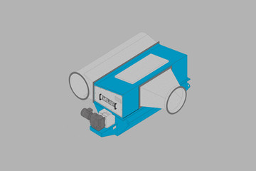

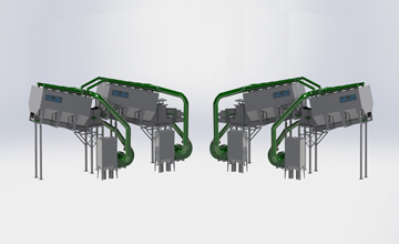
The Walair Drum Separators
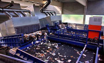
The Drum Separators from Walair are used in the recyclingindustrie to split/separated a waste flow in 2 waste streams. A heavy and a light fraction.
Applications
The Walair Drum Separator`s are used in the recyclingindustry to split/separate a waste flow in 2 waste streams. A heavy and a light fraction.
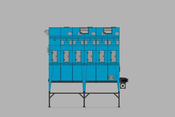
Designs/Specifications
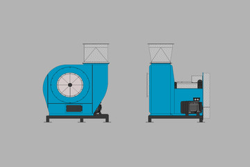
The Walair Drum Separators are made in several width sizes the fan separators are made in capacities from 12.000m3/h till 45.000 m3/h.
The separating drums are made in a diameter from 1000 mm and 650 mm.
The conveyor width from the unit are made from 1200 mm till 2000 mm. The unit can handle waste streams until aprox. 70 tons/hour (250 kg/m3).
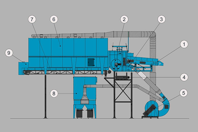
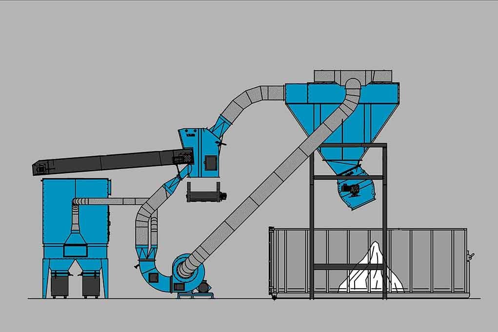
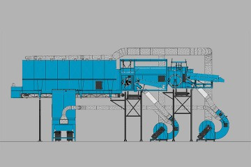
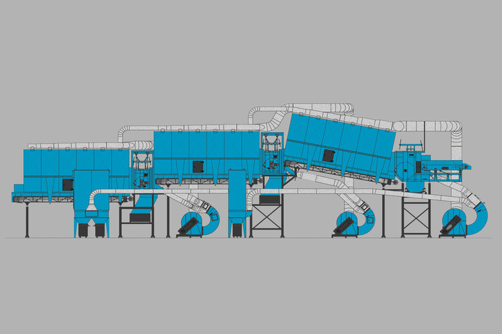
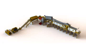
1. speedupband 2. roterende drum 3. blaasmond 4. afvoerband zware fractie 5. ventilator scheider 6. expansiekamer 7. afvoerband expansiekamer 8. stoffilter 9. ontstoffing expansiekamer
Working of the Walair Drum Separators
Behind the input conveyor a special speed-up conveyor is placed, which transports the input fraction into the Drum Separator (1).
You have to take care of a frequency regulator, to regulate the speed of the conveyor between 80 – 120 mtr/min.
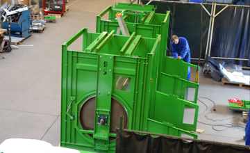
The conveyor is adjustable in a horizontal and vertical position and in an angle. Below the conveyor a blow mouth (3) is installed. The blow mouth is also adjustable in a horizontal and vertical position and in an angle. To adjust the air flow, the blow mouth is executed with 2 air regulation valves. Behind the charge conveyor an expansion room with a rotating drum (2) with a diameter of 1000 mm. is installed.
In the expansion room, using the blowing capacity of the blow mouth and the suction capacity above the separating drum, the heavy and the lighter fraction will be separated.
Both the inlet, as the distance to the drum till the discharge chute to the expansion room (6), can be adjusted in height.
Along the front of the drum, the heavy fraction is, by means of a chute, discharged to a discharge conveyor (4). The discharge conveyor is not part of our delivery.
The lighter fraction is blown over the separation drum and extracted and discharged to the expansion room (6).
In this expansion room the air is separated from the material.
Below the sedimentation room a discharge conveyor is installed. (7)
To create a suction flow above both the separation drum, the expansion room is executed with internal boxes which are, by means of 2 suction ducts, connected to one fan separator (5). The fan will suck for 100% at the sedimentation room.
In the fans the air is separated in an air dust flow of approx. 20% and a blow air flow of approx. 80% and is used to blow the fraction against and over the separation drum.
The air dust flow (20%), containing the dust, is discharged to a dust filter (8).
The fan separator (5) is executed with two regulation valves. These valves determine the amount of air to the blow mouth (3) and the amount of air which must be discharged to the dust filter (8).
Using these possibilities and the possibilities to adjust the speed-up conveyor of the drum separator horizontal and vertical and in an angle, it is possible to adjust the unit to the necessary input flows and fraction sizes.
The special fan separators (5) allow the installation of a relative small dust filter, due to the circulation of mostly the biggest part of the air.