Other Products


The Walair 3-way Drum splitter
The Walair 3-way Drum splitter especially is made to split a waste stream in 3 separate waste streams.
Applications
Designs/Specifications
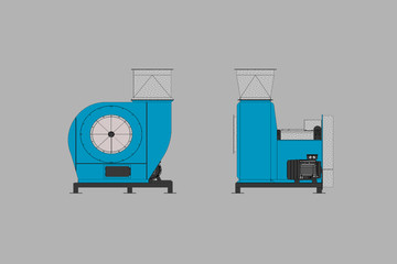
Walair is producing a three way separator and a three way splitter.
The three way splitter especially is made to split a waste stream in 3 waste streams.
Heavy, middle and light fraction. The unit is made in several waste sizes and made in conveyor width of 1200 mm till 2000 mm. The unit can handle waste streams max. till 70 tons/hour (250 kg/m3)
The separation result is not so precise as the Walair 3-way Drumseparator.
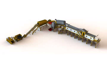
The unit is compact and can easily be integrated in a waste handling installation.
The separation rooms, blowingmouth and air capacity are complete adjustable.
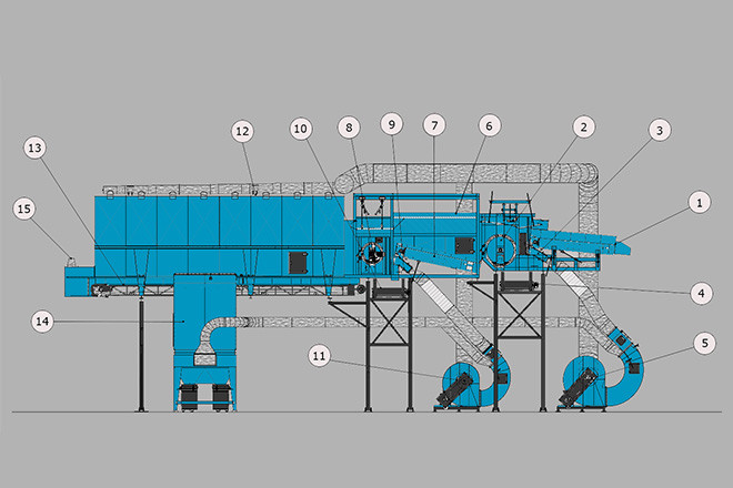
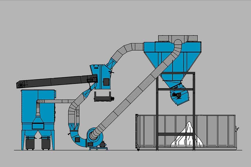
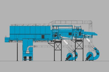
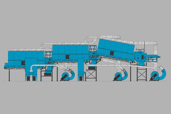
1. speedup conveyor 2. rotating drum 3. blowing mouth 4. conyeyor heavy fraction 5. fan separator 6. expansionroom 7. conveyor expansionroom 8. second rotating drum. 9. second blowing mouth 10. conveyor middle heavy. 11. second fan separator. 12. second expansionroom. 13.conveyor second expansionroom 14. dustfilter 15. dustextraction point
Working principle of the 3-way Drum splitter
After the screen with discharge conveyor the input fraction will be imported to a fast running speedup conveyor (nr 1).
The conveyor is adjustable in a horizontal and vertical position and in an angle.
We advise to supply the conveyor with a frequency regulator, so the speed can be adjusted between 1 – 2.2 m/sec.
Below the conveyor a blow mouth (nr 3) is installed. The blow mouth is adjustable in a horizontal and vertical position and in an angle. To adjust the air flow, the blow mouth is executed with 2 air regulation valves and can be adjusted in angle.
The speedup conveyor is air tide connected to a separation room with a rotating heavy metal drum (nr 2) with a diameter of 1000 mm.
In the separation room (nr 6), using the blowing capacity of the blow mouth and the suction capacity above the separating drum, the heavy fraction is removed from the middle heavy and the light fraction. The sealing of the separation room can be adjusted in height. Both the inlet, as the distance to the drum till the discharge chute to the expansion room (6), can be adjusted in height and angle. Along the front of the drum, the heavy fraction is, by means of a chute, discharged to a discharge conveyor (nr 4).
In the separation room the middle heavy and the light fraction is blown and extracted over the drum and discharged into the small expansion room (6).
In this expansion room the air is separated from the middle heavy and the light fraction.
Under the expansion room a discharge conveyor (nr 7) transports the middle heavy and the light fraction to a second drumseparator.
This separator also consists of a separation drum diam. 650 mm (nr 8) and a blow mouth (nr 9).
Both the inlet, as the distance to the drum till the discharge chute to the expansion room (6), can be adjusted in height and angle.
The middle heavy fraction is, by means of a chute, discharged to a discharge conveyor (nr 10).
The light fraction is separated in the separation room and blown and extracted over the drum and discharged in the second expansion room (nr 12).
Below this sedimentation room a discharge conveyor (13) is mounted.
To create a suction flow above the separation drum, both the expansion rooms are executed with 2 extraction ducts which are, by means of two suction ducts connected to two fan separators (nr 5 and nr 11). One fan for each separator. The fans extract for 100% the air out of the two expansion rooms. In the fans the air is separated in an air dust flow of approx. ± 20%, and a blow air flow of ± 80%.
With the blow air flow the fraction is pushed against and over the separation drum. The air dust flow (20%), containing the dust, is discharged to the dust filter (nr 15).
The fan separators (nr 5 and nr 11) are executed with two regulation valves or are connected to a frequency regulator. So it is possible to adjust the amount of air to the blow mouth (nr 3 and nr 9) and the amount of air which must be discharged to the dust filter (nr 15).
By using these possibilities and the adjustments on the speed-up conveyor of the drumseparator and adjustment possibilities on the second drumseparator, the 3-way drum splitter can easily be adjusted for different input flows and fraction sizes.
The special fan separators (5 and 11) allow the installation to work with a relatively small dust filter, due to the circulation of ± 80% of the total air capacity.